Reliable network connectivity is crucial in modern industrial and commercial environments. The RJ45 DIN rail terminal block plays a pivotal role in achieving this, offering a robust and organized solution for network cabling within control cabinets and similar enclosures. This specialized component, often referred to as an Industrial RJ45 Breakout Module, facilitates the secure and efficient termination of Ethernet cables.
This Ethernet Terminal Wiring Guide will detail the installation and wiring procedures for RJ45 DIN rail terminal blocks, highlighting essential considerations for optimal performance and reliability.
Part 1.Preparation and Required Tools
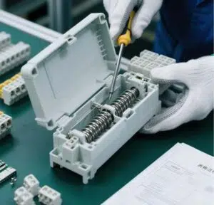
Before commencing installation, ensure all necessary tools and materials are on hand to facilitate a smooth and safe process. For this Ethernet Terminal Wiring Guide, you’ll typically need a standard toolkit including:
- Wire cutters: For clean cable trimming.
- Wire strippers: Specifically for network cables (Cat5e/Cat6) to expose individual conductors without damage.
- Small flat-head screwdriver: Essential for tightening the screw terminals on the Industrial RJ45 Breakout Module.
- DIN rail cutters (optional): If you need to cut DIN rail to size.
- Continuity tester: For verifying connections after wiring.
Materials: Confirm you have the correct RJ45 DIN rail terminal blocks, sufficient lengths of appropriate network cable (e.g., Cat5e, Cat6), and any additional cable management accessories.

Safety Precautions: Always prioritize safety. Disconnect power to any active circuits in the cabinet before beginning work. Wear appropriate personal protective equipment (PPE), such as safety glasses. Adhering to these guidelines will prevent accidents and ensure a successful installation.
Part 2.Installing the RJ45 DIN Rail Terminal Block
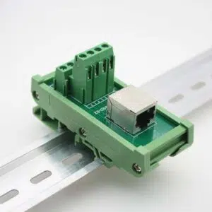
The installation of an RJ45 DIN rail terminal block, or Industrial RJ45 Breakout Module, is a straightforward process designed for efficiency and reliability within control panels. The overall procedure involves securely mounting the module onto the DIN rail, then preparing and terminating the network cabling.
To fix the terminal block, simply align the module’s integrated mounting clip with the top edge of the 35mm DIN rail. Press down firmly until you hear or feel a “click,” indicating that the bottom of the clip has engaged the rail. This ensures a stable and vibration-resistant connection crucial for maintaining network integrity.
Proper grounding and electrical safety are paramount. While RJ45 connections are inherently low-voltage, it’s good practice to ensure the overall DIN rail system, and thus connected modules, are adequately grounded if required by your specific application or local electrical codes. Some modules may feature a dedicated ground terminal for enhanced safety. Always verify that power is disconnected before handling any wiring, mitigating the risk of electrical shock and ensuring a safe installation environment.
Part 3.Wiring the RJ45 Connector:A Step-by-Step Guide
Properly wiring your network cable to an Industrial RJ45 Breakout Module is crucial for optimal network performance. Here’s how to ensure a reliable connection:
1. Cable Preparation:
Begin by cutting your network cable to the necessary length. Use a dedicated cable stripper to remove about 1 to 1.5 inches of the outer jacket. Be careful not to damage the inner twisted pairs. Once stripped, untwist and straighten each of the eight individual wires.
2. Adhere to Wiring Standards:
Consistency is key. Choose either the T568A or T568B wiring standard for your RJ45 connections. While both are functional, T568B is more prevalent in commercial settings. For a straight-through cable (device to switch), both ends should use the same standard. For a crossover cable (device to device), one end uses T568A and the other T568B.
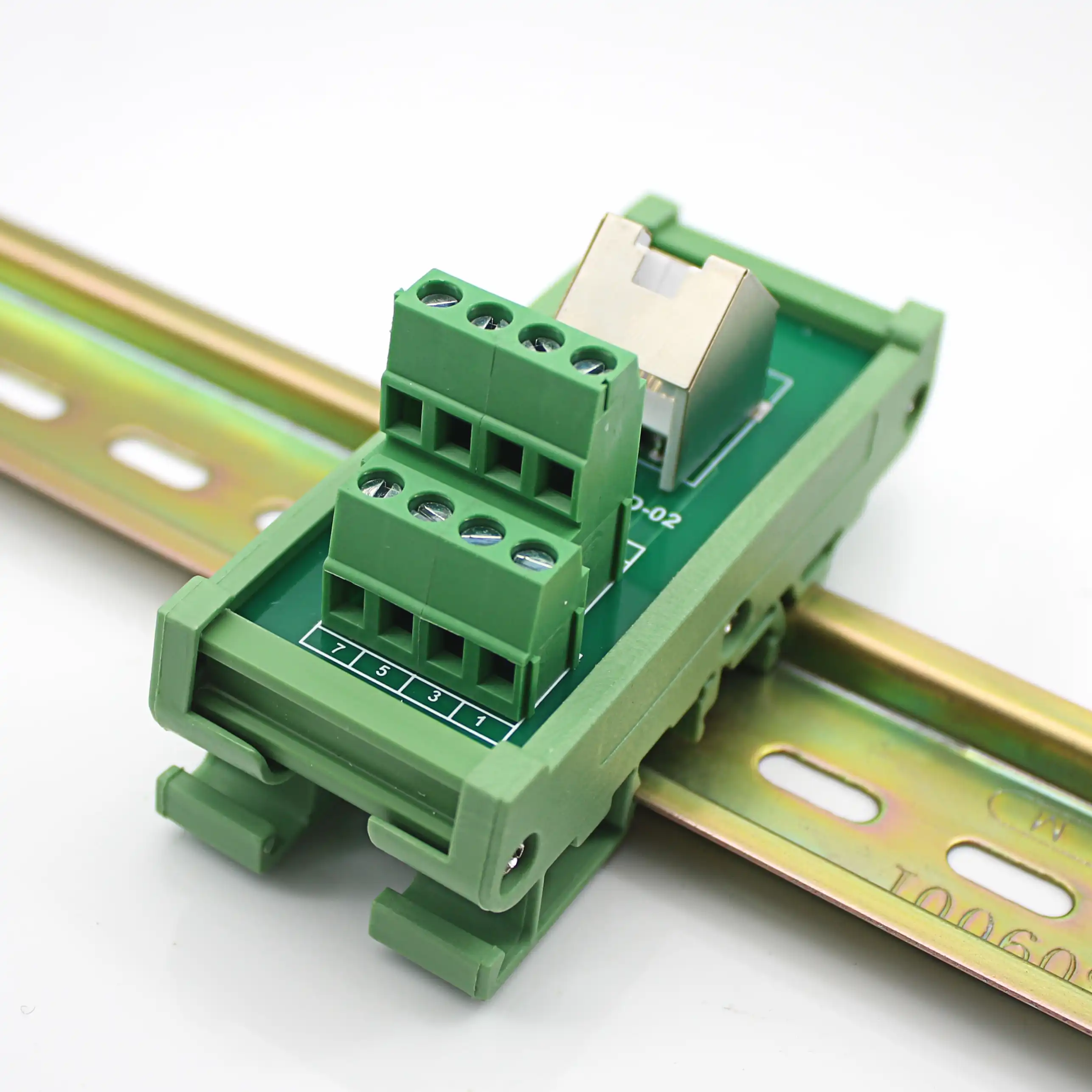
3. Connect Wires to Terminals:
Following your chosen standard, carefully insert each colored wire into its corresponding screw terminal on the module. Securely tighten each screw, ensuring no stray wire strands could cause short circuits.
4. Verify and Test:
After all wires are terminated, thoroughly inspect your work. Confirm that each wire is correctly seated and the color sequence matches your chosen standard. Finally, use a network cable tester to verify proper continuity and check for shorts, guaranteeing reliable signal transmission.
Part 4.Testing and Troubleshooting
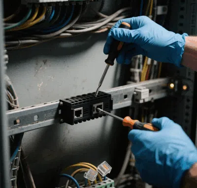
After installing and wiring your Industrial RJ45 Breakout Module, thorough testing is crucial for stable network connectivity. A network cable tester is the primary tool. Connect one end to the module’s RJ45 jack and the other to your network device or patch panel. The tester verifies wire sequence (T568A/B), identifies open circuits, shorts, or split pairs, ensuring signal integrity. For advanced diagnostics, a network analyzer can assess packet loss, latency, and throughput.
Common problems and solutions include:
Should issues arise, systematic troubleshooting is key.
- No Link Light/Signal Loss:This usually points to a wiring error. Double-check all individual wire terminations at the screw terminals against your chosen T568A/B standard. Make sure all screws are tight and there are no stray copper strands causing shorts.
- Intermittent Connection:Verify the cable jacket is securely seated in any strain relief. Also, ensure the DIN rail module is firmly mounted; vibrations can easily disrupt connections.
- Incorrect Speed Negotiation:Confirm both the network device and the module are rated for your desired network speed (e.g., Gigabit Ethernet) and that your cable (e.g., Cat6) supports it.
Following these steps helps quickly resolve most connectivity issues, ensuring reliable network operation.Should any issues or questions arise while troubleshooting, please don’t hesitate to contact AOSI supplier. Our team of professionals is ready to provide expert assistance and solutions.
Part 5.Maintenance and Care
Regular Maintenance: Key to RJ45 DIN Rail Stability
Periodically, visually inspect all connections on the Industrial RJ45 Breakout Module. Ensure all screws remain tightly fastened, with no signs of corrosion or discoloration on wire terminations. Check for any physical damage to the module housing or the RJ45 port itself. Additionally, gently tug on individual cables to verify they’re securely seated, which mitigates the risk of intermittent connectivity from vibration or accidental dislodgment.
Environmental Care for Your RJ45 DIN Rail Modules
Maintaining a clean, protected environment for network components is vital. Dust and moisture degrade connections, causing signal loss or equipment failure. Use a soft, lint-free cloth and specialized electronic cleaning solution to gently clean the module’s exterior; avoid abrasives or excessive moisture. Ensure the cabinet housing the modules is adequately sealed and climate-controlled, preventing dust, humidity, and extreme temperatures.
Following this Ethernet Terminal Wiring Guide for environmental care will significantly extend the operational life and reliability of your network infrastructure.

Conclusion
This guide outlined the professional installation of Industrial RJ45 Breakout Module—key to industrial network reliability. From DIN rail mounting and T568A/B wiring to testing and maintenance, precision ensures stable connectivity and reduced downtime.
As industrial automation and smart infrastructure evolve, these modular blocks remain vital for high-bandwidth and scalable networks.
Upgrade your system with AOSI’s high-performance DIN rail solutions. Explore our industrial-grade RJ45 terminal blocks and expert support—optimized for durability and ease of deployment.
Visit AOSI today for tailored connectivity solutions that keep your network future-ready.