
Part1. What to Check Before You Start Installing?
This chapter focuses on the preparatory work before installing pluggable terminal blocks, emphasizing the need to check electrical compatibility, wire condition, and ensure the availability of necessary tools to lay a solid foundation for a smooth installation.
Electrical Compatibility
Before diving into the installation of pluggable terminal blocks, it’s crucial to verify the compatibility of the terminal block with your electrical system. Check the voltage and current ratings. If the ratings don’t match, it could lead to overheating or even electrical failures. For example, if your system operates at a high current, using a terminal block with a low current rating is a recipe for disaster.
Wire Condition
Examine the wires you’ll be using. They should be free from any visible damage like cuts or fraying. Damaged wires can cause poor connections or short circuits. Ensure the insulation is intact and in good condition. If you notice any issues, replace the wires before installation.
Tools Availability
Make sure you have all the necessary tools at hand. For screw – type terminal blocks, you’ll need a suitable screwdriver. Different terminal blocks may require specific tools, so double – check what’s needed. Having the right tools will make the installation process much smoother.

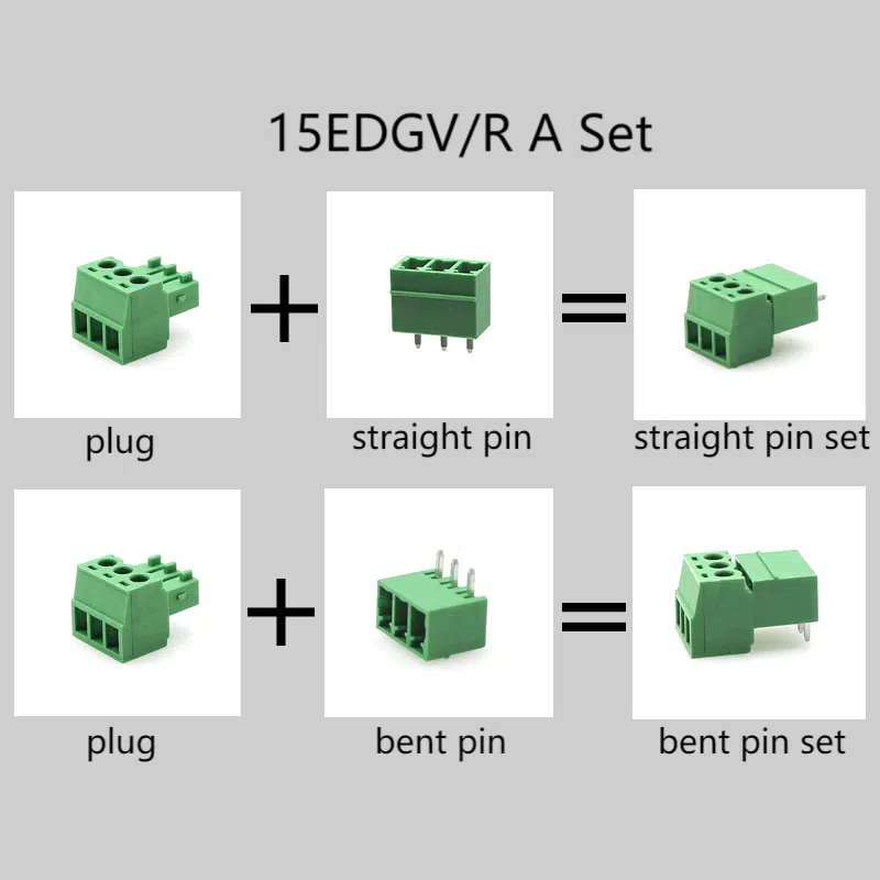
Part2. Pluggable Terminal Block for PCB, DIN Rail & Wall Installation
PCB Pluggable Terminal Blocks
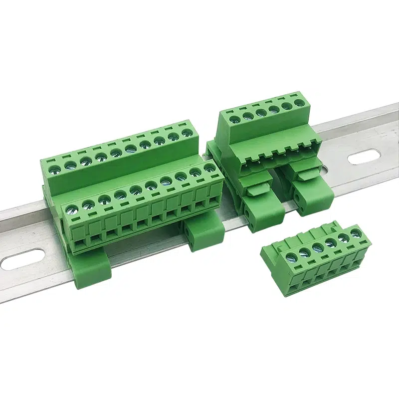
DIN Rail Pluggable Terminal Blocks
DIN Rail pluggable terminal blocks are widely used in industrial control panels. Their advantage lies in their easy installation. You can simply snap them onto the DIN rail. This allows for quick installation and replacement if needed. They are also great for organizing and managing a large number of wires in an industrial setting.
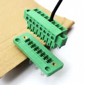
Wall Through Plug In Terminal Blocks
Wall through plug In terminal blocks are suitable for situations where a wall – mounted connection is necessary. They provide a secure and accessible way to connect wires through walls. When installing them, make sure to follow the proper installation procedures to ensure a watertight and secure connection, especially if used in outdoor or damp environments.
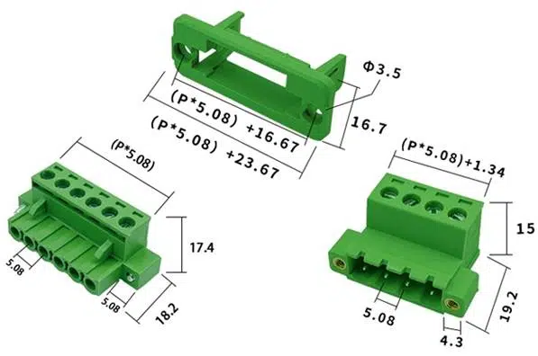
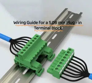
Part3. Step - by - Step Guide to Wiring a 5.08 mm Plug in Terminal Block
Step 1: Prepare the Wires
Start by stripping the insulation from the wires to the appropriate length. This length is usually specified by the manufacturer of the terminal block. Use a wire stripper to carefully remove the insulation without damaging the wire strands inside.
Step 2: Open the Clamping Mechanism
Locate the clamping mechanism on the 5.08 mm plug in terminal block. Use the appropriate tool, if required, to gently open it. This will create space for the wire to be inserted.
Step 3: Insert the Wire
Take the stripped wire and firmly insert it into the terminal. Make sure the wire goes in all the way and is properly seated in the terminal.
Step 4: Close the Clamping Mechanism
Once the wire is in place, close the clamping mechanism to secure the wire. Apply the right amount of force to ensure a tight connection, but be careful not to over – tighten.
Step 5: Repeat for All Wires
If you have multiple wires to connect, repeat the above steps for each wire. For a more visual understanding, check out this video below:
Part4. Quick Checks and Tests After Installing
This section introduces the quick check and test methods after installing pluggable terminal blocks, including visual inspection, electrical continuity test, and temperature check, to ensure the installation quality.
Visual Inspection
After installing the pluggable terminal blocks, perform a visual inspection. Check that all connections are tight and there are no loose wires. Look for any signs of misalignment or damage to the terminal blocks themselves.
Electrical Continuity Test
Use a multimeter to test the electrical continuity. This will help you confirm that the wires are properly connected and that electricity can flow through the circuit as expected. If there’s no continuity, you may need to recheck the connections.

Temperature Check
After a short period of operation, feel the terminal blocks gently. They should not be overly hot. Excessive heat could indicate a poor connection or overloading. If you notice any abnormal heating, investigate further.
FAQ — Installing Pluggable Terminal Blocks
How do I install pluggable terminal blocks on control panels without shutting the whole panel down?
Isolate only the circuit you’re working on, mount the block to the DIN rail, pre-wire leads, then re-energise that circuit. This keeps the rest of the control panel live and productive.
Can you give me a quick step-by-step guide to wiring a 5.08 mm pluggable terminal block?
Strip 6–7 mm of insulation, insert the conductor fully, tighten to the specified torque (≈0.5 Nm), verify with a gentle pull test, label the position, and repeat for every pole before plugging the header into its mating socket.
What are the common mistakes when installing plug-in terminal blocks?
Under-torqued screws, mixing incompatible wire sizes, reversing pin-1 orientation, skipping continuity checks, and failing to re-torque after thermal cycling are the top culprits.
Do DIN-rail and PCB versions require different tools?
Yes. DIN-rail models usually need only a flat-blade screwdriver and rail cutter, while PCB plug-ins call for a soldering iron or selective-solder machine plus optical inspection.
How often should I re-torque connections once everything is wired?
Recheck after the first 24 hours of operation and every six months thereafter, especially in high-vibration or wide-temperature environments.
Conclusion
With solid preparation, precise wiring, and diligent post-installation tests, your pluggable terminal blocks will deliver reliable power and signal transfer for years. Ready for the next project? Explore our full range of pluggable terminal blocksto find the perfect match for your design.