


Extending encoder signal distance without degradation is vital for ensuring accurate position feedback in large-scale automation systems. However, encoder signals are prone to attenuation and noise over long cable runs.
This article explains the underlying physical causes, common wiring mistakes, and practical solutions—highlighting opto-isolated modules and signal boosters that preserve signal integrity.
Why Encoder Signals Fade Over Long Cables
Encoder signals weaken for physical reasons related to cable capacitance and resistance. The longer the wire, the greater the total resistance, which causes voltage drops along the line. At the same time, capacitance between conductors smooths out the fast edges of square pulses, effectively acting as a low-pass filter.
As a result, logic levels become uncertain — what should be a sharp 5 V signal becomes a sluggish 3 V waveform that the PLC may misread.
This effect is especially visible in 24 V TTL encoders, where signal shape degradation begins to appear beyond 10 meters. At higher pulse frequencies, distorted waveforms can cause jitter, missed counts, or false triggering.
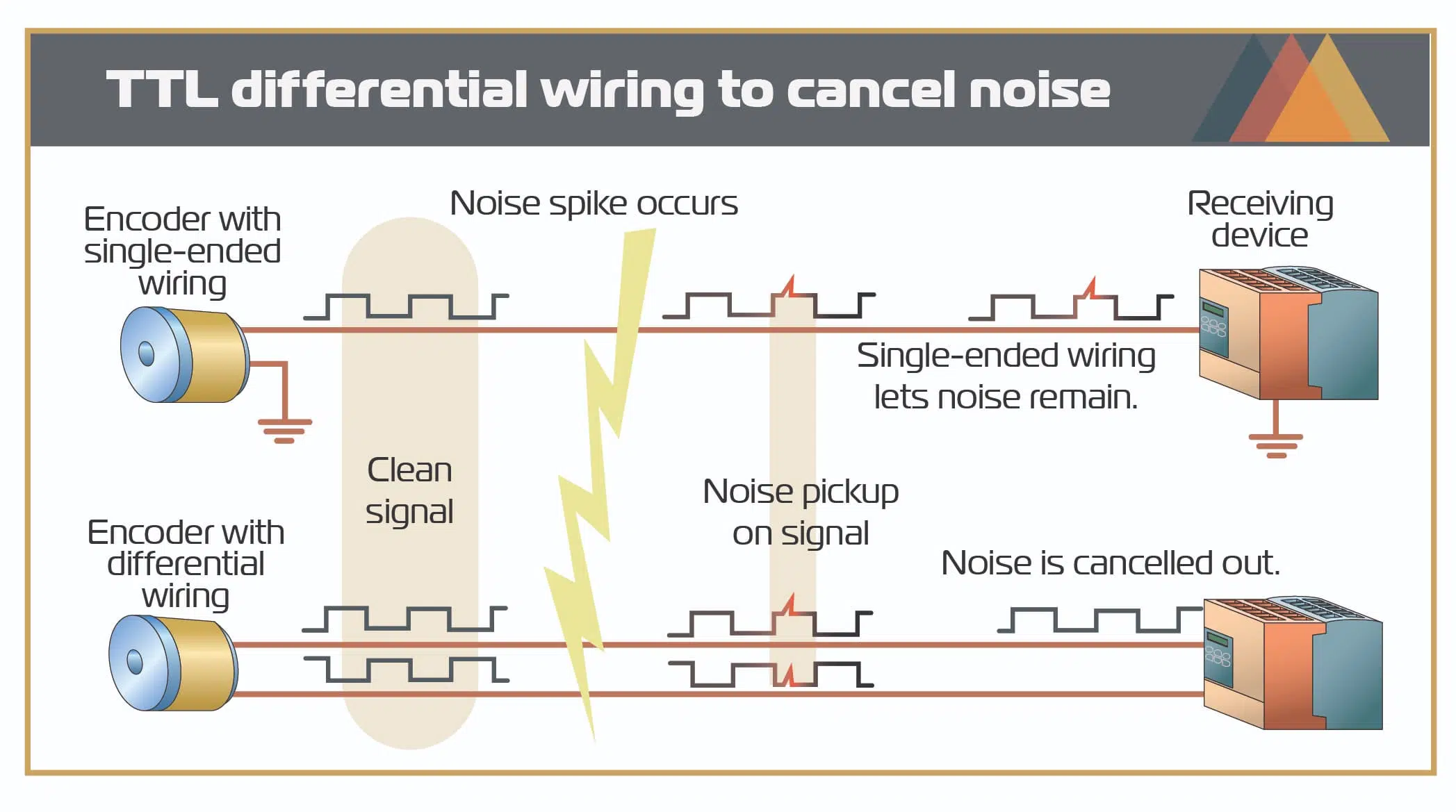
Additionally, long cables act as antennas, picking up EMI from nearby power wiring, motors, or contactors. This unwanted coupling leads to random pulse noise and inaccurate positioning.
Common Wiring Mistakes Over Long Distance
Extending encoder wiring seems simple — just add more cable — but several mistakes can ruin signal integrity.
- Parallel connections (Y-split wiring)
Many installers try to feed one encoder into multiple PLCs directly. This increases cable capacitance and impedance mismatch, creating reflections and noise.
→ For proper multi-device setups, see our guide How to Split Encoder Signals Safely. - Thin wire gauge
Using wires that are too small increases resistance. Over 20 m, voltage drop can exceed 0.5 V, weakening the logic signal. Always use at least 0.5 mm² (24 AWG) conductors. - Poor shielding and grounding
Unshielded cables are vulnerable to interference. Ground shields at one point only (usually at the controller) to avoid ground loops. - Routing near power cables
Encoder lines placed parallel to motor cables pick up inductive noise. Maintain 10 cm separation or run through metal conduit. - Ignoring cable capacitance
High-resolution encoders output fast pulses; choose low-capacitance twisted-pair cable rated for data transmission to maintain edge sharpness.
For setups requiring multiple receivers, proper distribution is critical. Refer to our guide on How to Split Encoder Signals Safely to avoid multi-device wiring pitfalls and ensure consistent signal quality across controls.
How Opto-Isolated Modules Maintain Signal Quality
For long-distance encoder wiring, a pulse amplifier or opto-isolated module is the most effective solution.
How It Works
An opto-isolator converts each electrical pulse into light, transfers it across an optical barrier, and rebuilds it electronically on the output side. This breaks ground continuity, eliminating noise from ground-potential differences.
At the same time, an internal line driver restores signal voltage and timing to RS422 standards, capable of cleanly transmitting another 20–30 meters.
Key Benefits
- Noise rejection: Isolation removes ground-loop interference.
- Voltage restoration: Each output channel is regenerated to full amplitude.
- System safety: Protects encoders and PLC inputs from surges or mis-wiring.
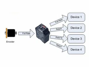
- Scalability: Multiple isolated outputs can feed several controllers independently.
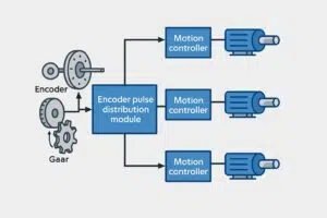
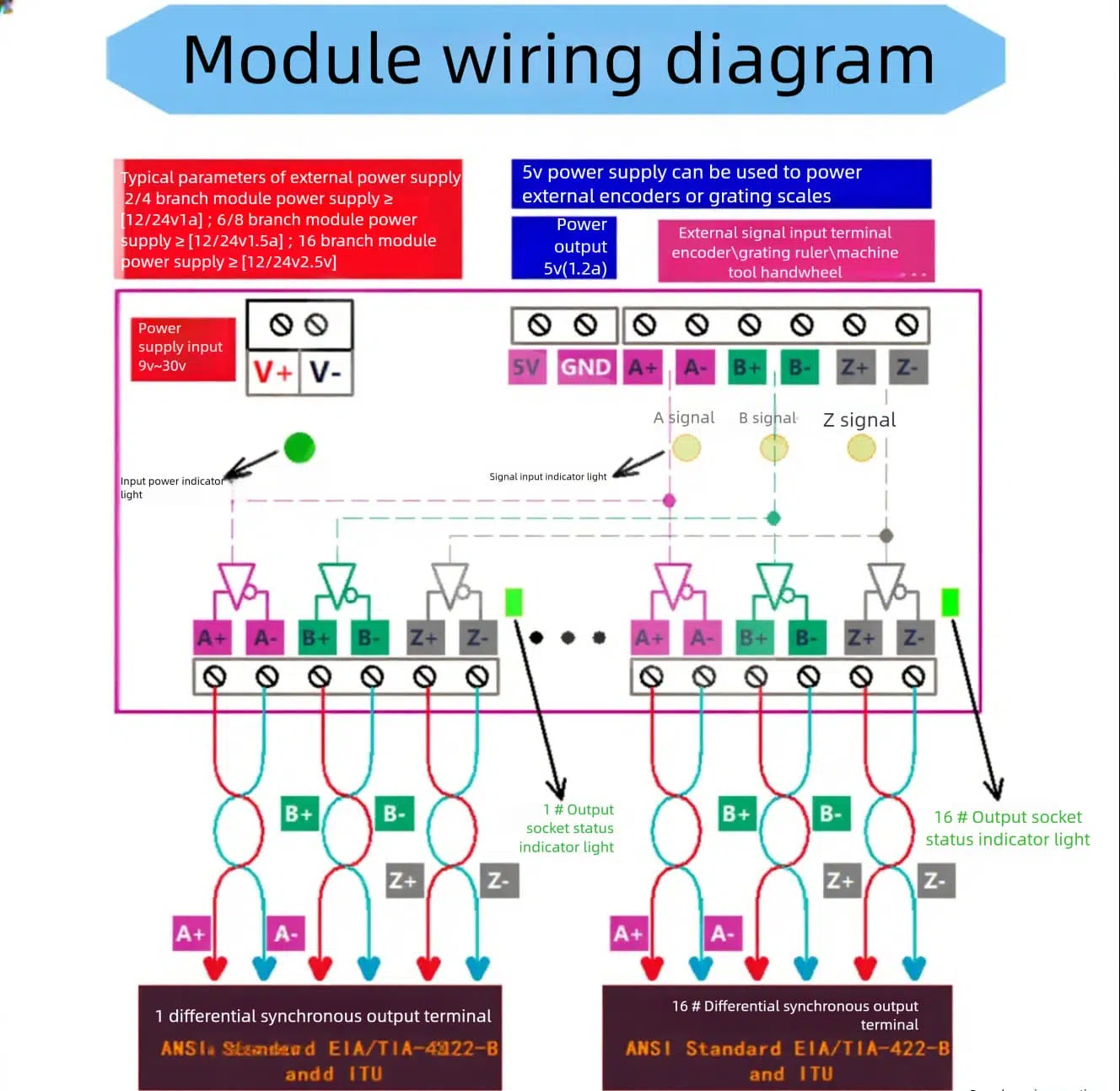
ABZ Encoder Pulse Distribution Modules
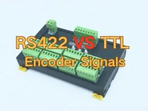
- Supports RS422 and TTL Differential Output
- Eight Isolated Channels with LED Indicators
- DIN-rail mount for control cabinets
This compact booster regenerates encoder ABZ pulses and delivers synchronized, isolated differential outputs, ensuring clear transmission over long cables in noisy environments.
Wiring Layout Example
A recommended layout for long-distance encoder wiring is:
Encoder → ABZ Encoder Pulse Distribution Modules → Remote PLC
- Encoder Side – Keep the initial cable short (under 2 m) and shielded.
- Cable Run – Use twisted-pair conductors for each differential signal (A+/A–, B+/B–, Z+/Z–). Maintain proper shielding and separation from power cables.
- PLC Side – Ground the shield at one point only and connect differential inputs directly to PLC encoder terminals.
This configuration preserves edge clarity and eliminates reflections even on 30 m cable lengths.
Case Study – Long Conveyor Feedback Loop
A packaging facility faced encoder signal degradation on a 20-meter conveyor feedback loop, resulting in lost pulses and faulty product counts. After installing an AOSI Differential ABZ Distribution Modules near the encoder, the system achieved flawless pulse integrity downstream.
This upgrade led to:
- Accurate pulse counts across the entire conveyor length
- Elimination of erratic stops and alarms
- Reduced maintenance and troubleshooting efforts
Such a setup is essential where long physical distances separate encoder feedback from control hardware, especially in automation, robotics, and material handling sectors.
By understanding and applying noise mitigation, proper wiring, and signal extending modules like opto-isolation boosters, you can reliably extend encoder signal distance without compromising system performance.
FAQs
A1: Signal attenuation due to cable capacitance and resistance degrades encoder pulses, especially beyond 10 meters for TTL outputs. Electrical noise and improper shielding accelerate signal loss and distortion.
A2: Standard TTL encoders work best under 10 meters. Beyond that, waveform distortion occurs. Using a signal amplifier or RS422 driver is recommended for longer runs.
A3: Use an opto-isolated pulse amplifier module or RS422 line driver. These devices regenerate the ABZ signals, restore voltage, and eliminate ground noise for stable long-distance transmission.
A4: Not directly. Use a pulse distribution or ABZ-splitter module for safe, buffered signal routing to multiple devices, preventing phase errors and signal reflection.
A5: Typical errors include using thin wire gauge, parallel Y-split wiring, poor shielding, or grounding at both ends. These mistakes cause voltage drop, reflection, and EMI interference.
A6: Yes. A multi-channel opto-isolated signal booster module can safely split and strengthen encoder outputs for several PLCs or controllers, ensuring synchronized, interference-free feedback.
Conclusion
For short cables under 5 m, TTL encoders may suffice. For any distance beyond that — especially in industrial environments — use RS422 differential transmission or an opto-isolated signal booster module.
By combining proper cable selection, shielding, and isolation, engineers can confidently extend encoder signal distance while maintaining precision, stability, and long-term reliability.